This cables are mainly used in power stations, mass transit underground passenger systems, airports, petrochemical plants, hotels, hospitals, and high-rise buildings.
Basic design to BS EN 50525-2-31(formerly BS 6004:2000)
| Flame Retardance (Single Vertical Wire Test) | EN 60332-1-2 |
300/500V
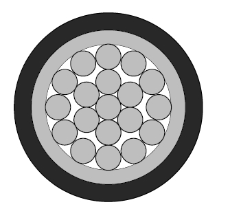
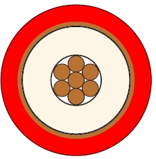
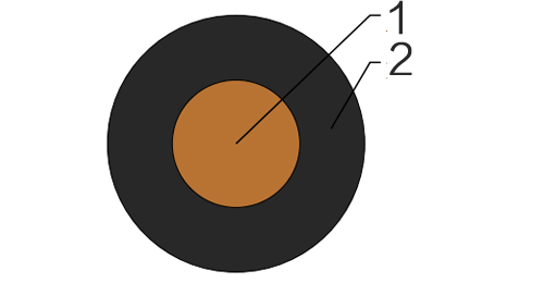
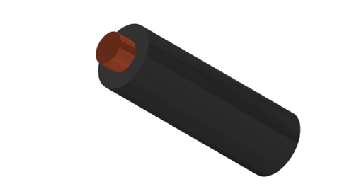
| Conductor | H05V-U | Class 1 solid copper conductor to BS EN 60228. |
| H05V-R | Class 2 stranded copper conductor to BS EN 60228. | |
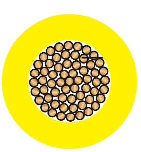
| H05V-K | Class 5 stranded copper conductor to BS EN 60228. | |
| Insulation | PVC Type TI 3 according to BS EN 50363-3 | |
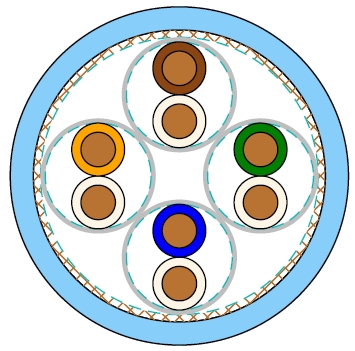
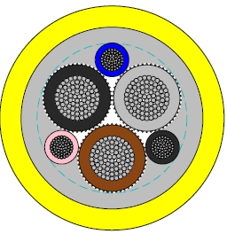
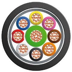
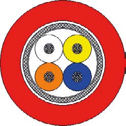
Black, Blue, Brown, Grey, Orange, Pink, Red, Turquoise, Violet, White, Green and Yellow. Bicolours of any combination of the above mono-colours are permitted.
| Maximum temperature range during operation (PVC) | 90°C | |
| Maximum short circuit temperature (5 Seconds) | 160°C | |
| Minimum bending radius | Up to 8mm² | 4 x overall diameter |
| 8mm² to 12mm² | 5 x overall diameter | |
| Above 12mm² | 6 x overall diameter | |
| Conductor | FLP300-V2-U/R/K | |||
|---|---|---|---|---|
| No. of Cores x Cross Section | Class of Conductor | Nominal Insulation Thickness | Maximum Overall Diameter | Approx. Weight |
| No.xmm² | mm | mm | kg/km | |
| 1x0.50 | 1 | 0.6 | 2.3 | 8 |
| 1x0.75 | 1 | 0.6 | 2.5 | 11 |
| 1x1.0 | 1 | 0.6 | 2.7 | 14 |
| 1x0.50 | 2 | 0.6 | 2.4 | 9 |
| 1x0.75 | 2 | 0.6 | 2.6 | 12 |
| 1x1.0 | 2 | 0.6 | 2.8 | 14 |
| 1x0.50 | 5 | 0.6 | 2.5 | 8 |
| 1x0.75 | 5 | 0.6 | 2.7 | 11 |
| 1x1.0 | 5 | 0.6 | 2.8 | 13 |
| Conductor cross-sectional area | PVC insulated types (HD 21) | |
|---|---|---|
| single-phase a.c. | three-phase a.c. | |
| mm² | A | A |
| 0.50 | 3 | 3 |
| 0.75 | 6 | 6 |
| 1.0 | 10 | 10 |
Note: These values apply to the majority of cases. Further information should be sought in unusual cases eg.: (i) When high ambient temperatures are involved, ie. above 30°C (ii) Where long lengths are used (iii) Where ventilation is restricted (iv) Where the cords are used for other purposes, ego internal wiring of apparatus. | ||
| Nominal Cross Section Area | 2 cables d.c. | 2 cables, single-phase a.c. | 3 or 4 cables, three-phase a.c. | |||||
|---|---|---|---|---|---|---|---|---|
| Ref. Methods A and B (enclosed in conduit or trunking) | Ref. Methods C, F & G (clipped direct, on trays or in free air) | Ref. Methods A & B (enclosed in conduit or trunking | Ref. Methods C, F & G (clipped direct, on trays or in free air) | |||||
| Cables touching | Cables spaced* | Cables touching, Trefoil | Cables touching, Flat | Cables spaced*, Flat | ||||
| 1 | 2 | 3 | 4 | 5 | 6 | 7 | 8 | 9 |
| mm² | mV/A/m | mV/A/m | mV/A/m | mV/A/m | mV/A/m | mV/A/m | mV/A/m | mV/A/m |
| 0.50 | 93 | 93 | 93 | 93 | 80 | 80 | 80 | 80 |
| 0.75 | 62 | 62 | 62 | 62 | 54 | 54 | 54 | 54 |
| 1.0 | 46 | 46 | 46 | 46 | 40 | 40 | 40 | 40 |